 |
|||
|
|
|||
|
Page Title:
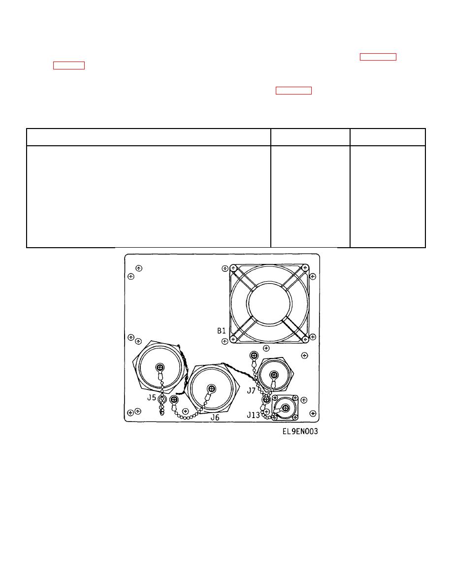
Figure 1-3. Encoder-Decoder Rear View |
|
||
| ||||||||||
|
|
 TM 11-5895-1179-13 EE132-EA-OMP-010/E106 KY883 TO 31Sl-2GSC-161
front panel assembly, rear panel assembly, and cover) encloses six circuit card assemblies identified in figure 1-2 and
listed in table 1-3. The back plane circuit card assembly is mounted on the rear panel assembly and contains four
receptacles for the plug-in-circuit card assemblies. The display and control circuit card assembly is mounted on the front
panel assembly. All controls and indicators for operation of the encoder-decoder are located on the front panel assembly.
The fan and all external connections are located on the rear panel assembly (figure 1-3).
Table 1-3. Encoder-Decoder Assemblies
Reference
Assembly
Designator
Drawing Number
Decoder Plug-In-Circuit Card Assembly
Al
SM-D-986495
Interleaver Plug-In-Circuit Card Assembly
A2
SM-D-986498
Input/Output Plug-In-Circuit Card Assembly
A3
SM-D-986492
Power Supply Plug-In-Circuit Card Assembly
A4
SM-D-882477
Rear Panel Assembly
A5
SM-D-986483
Backplane Circuit Card Assembly
A5A1
SM-D-986486
Front Panel Assembly
A6
SM-D-986481
Display and Control Circuit Card Assembly
A6A1
SM-D-986489
Bottom Panel Assembly
A7
SM-D-882483-1
Chassis Assembly
A8
SM-D-986475
Figure 1-3. Encoder-Decoder Rear View
1-5
|
|
Privacy Statement - Press Release - Copyright Information. - Contact Us |
