 |
|||
|
|
|||
|
Page Title:
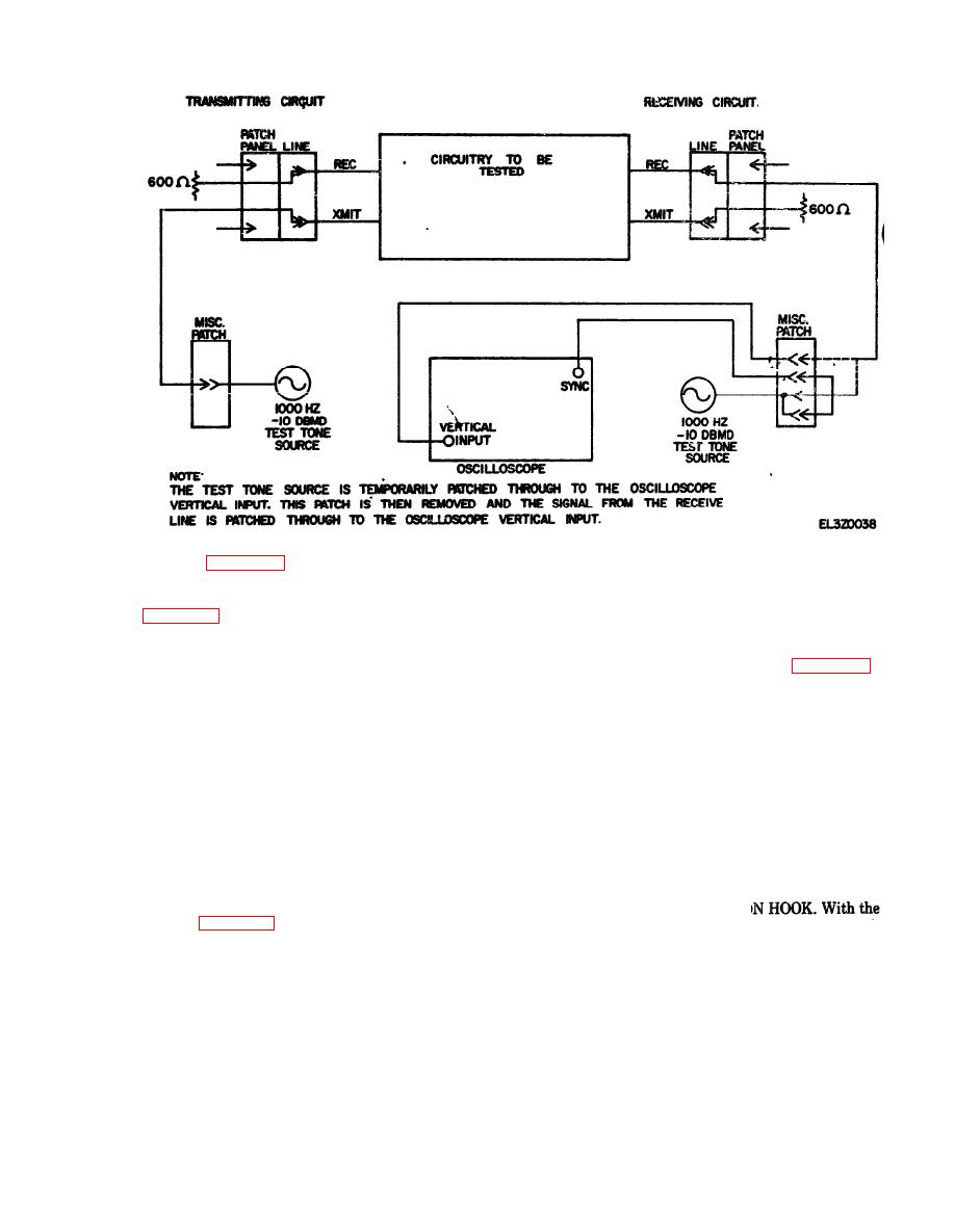
Figure 6-14. Phase jitter testing using an oscilloscope |
|
||
| ||||||||||
|
|
 TM 11-5895-1012-10
b. Teat Equipment. The following teat equipment
shown in figure 6-15.
required to perform this test:
(2) Receiving Circuit. If the local station is to act
(1) Signal Test Sets (2 required).
as receiver, prepare the receiving circuit shown in
(2) Terminating plugs (600 ohms) and patch cord
c. Teat Procedure. Contact distant station and a
(a) Power switch on.
(b) Impedance switch to 600 ohms.
range for one station to act as transmitter and one as
(c) Meter select switch to input level.
and perform the procedure below. Then reverse roles
(3) Procedures. At the receiving station, verify
and repeat the procedure.
that the input level is between +10 dbm and -40
(1) Place the controls of each signal test set as
dbm. Then switch the meter select switch to frequency
follows:
and verify that frequency lock has been achieved
(a) Send PPS selector to ON (10 PPS).
Switch the meter select switch to 30 P-P JITTER and
(b) Function switch to Test L & D.
read the meter indication of peak-to-peak phase jitter.
(c) TWD-L, LINE (E) key switch to OFF HOOK
( 4 ) P e r f o r m a n c e S t a n d a r d . T h e maximum
(d) TWD-D key switch to Thru & Meas.
permissable peak-to-peak phase jitter is 15 degrees.
(2) With the off hook signals being sent on the M
d. In-Station Test. In-station testing is ac-
lead at each station, the E lead at both ends should be
complished in the same manner as station to station
grounded as indicated by the extinguishing of the
testing except the local stations act as both trans-
mitter and receiver.
LINE (E) lamps.
(3) At both stations, switch the signal test set
TWD-L, LINE (E) key switch on O
on-hook signal being sent to the M lead at each end,
the E lead at both stations should be open as indicated
a. Purpose. This test determines signaling per-
by the LINE(E) lamp at both stations being lighted.
formance and compliance with the standard operating
(4) At the transmitting station, place the signal
requirements.
test set controls as follows:
NOTE
(a) Test-Send key switch to Send Osc.
Prior to performing this test, the circuit shall
(b) Meter circuit selector % Break Direct.
be aligned and conditioned to the required
(c) Receive selector to any position except Send
circuit characteristics and transmission levels
and Rec.
specified in the TSO.
|
|
Privacy Statement - Press Release - Copyright Information. - Contact Us |
