 |
|||
|
|
|||
|
Page Title:
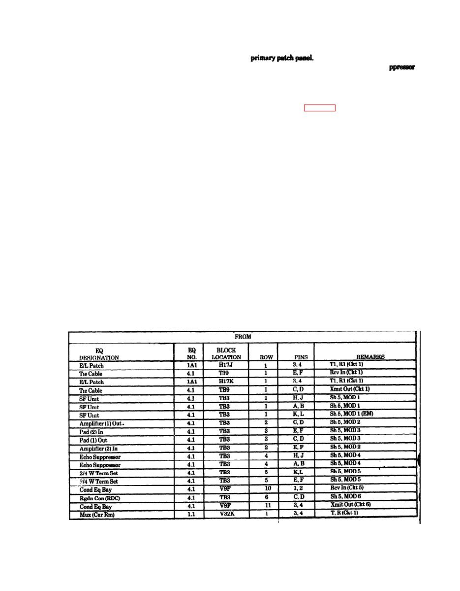
Table 4-7. Sample cutsheet for 2-wire voice circuit t (25 Hz signaling and echo suppressor control) |
|
||
| ||||||||||
|
|
 TM 11-5895-1012-10
line terminated at bay 4.1 on TB3, row 5, pins K and L
(4) The E&M/25 Hz converter and echo su
to the E&M/25 Hz ring down converter's Send In (T1,
has approximately 0 dB insertion loss and will not af-
R1) line terminated at bay 4.1 on TB3. row 6, pins A
fect the circuit levels.
and B by cross-connecting at buy 4.1, TB3, row 5, pins
c. In-Station Testing After the correct circuit levels
K and L, to TB3, row 6, pins A and B respectively.
have been obtained, perform the in-station test proce-
(13) Connect the 2/4 wire terminating set termi-
dures contained in chapter 6. To use a test on a 2 wire
nated at bay 4.1 on block TB3, row 5, pins E and F to
circuit, use the same two-wire circuit for both transmit
the VF primary patch panel terminated on block
and receive tests and omit the terminating resistor
H13K, row 1, pins 3 and 4 by cross-connecting at bay
when necessary.
4.1, TB3, row 5, pins 3 and F to TB9, row 5, pins E and
d. Multiplexer Equipment Connections. Refer to
F respectively and block V9F, row 10, pins 1 and 2 to
the sample cutsheet (table 4-7) and cross-connect as
block H13K, row 1, pins 3 and 4 respectively.
follows:
(14) Connect the E&M/25 Hz ringdown converter
(1) Connect the multiplexer receive circuit termi-
Receive In line terminated at bay 4.1 on TB3, row 6,
nated on block V32K, row 1, pins 3 and 4 to the equal
pins C and D to the VF primary patch panel equipment
level patch panel DEM IN (line) terminated on block
side (T1, R1) terminated on block H13K, row 1, pins 3
H17J, row 1, pins 1 and 2 by cross-connecting block
and 4 by cross-connecting at bay 4.1 TB3, row 6, pins
V32K, row 1, pins 3 and 4 to block H17J, row 1, pins 1
C and D to TB9, row 6, pins C and D respectively and
and 2 respectively.
block H13K, row 1, pins 3 and 4 to block V9F, row 11,
(2) Connect the multiplexer transmit circuit
pins 3 and 4 respectively.
terminated on block V32K, row 1, pins 1 and 2 to the
equal level patch panel MOD OUT (Line) terminated
Station test will be run before connecting to the multi-
on block H17K, row 1, pins 1 and 2 by cross-connect-
plexer equipment. Adjust levels from the equal level
ing block V32K, row 1, pins 1 and 2 to block H17J,
patch panel to the primary patch panel as follows:
row 1, pins 1 and 2.
(1) At the equal level patch panel, the receive and
c. Final Testing. Perform the out-of-service quality
transmit levels will be at 0 dBm.
control (station-to-station) testing contained in chap
(2) The SF-2600 has approximately 0 dB inser-
ter 6. If the circuit checks out in accordance with the
tion loss and will not affect the circuit level.
testing and conforms to established parameters, then
(3) Adjust amplifiers 1 and 2 for a 12 dB gain and
report the circuit ready for operation in accordance
pads 1 and 2 for an 8 dB loss to compensate for the 4
with established procedures.
dB insertion loss of the 4 wire termination set and al-
low an operation level of 0 dBm at the voice frequency
Table 4-7. Sample cutsheet for 2-wire voice circuit t (25 Hz signaling and echo suppressor control)
4-48
|
|
Privacy Statement - Press Release - Copyright Information. - Contact Us |
