 |
|||
|
|
|||
|
Page Title:
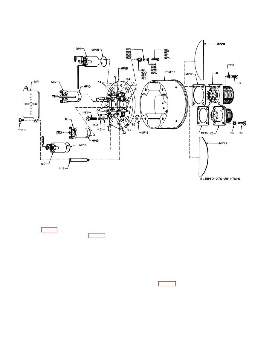
Figure 4-4. Mechanism assembly, exploded view. |
|
||
| ||||||||||
|
|
 TM 11-5840-270-24-1
Figure 4-4. Mechanism assembly, exploded view.
g. Remove window MP5 from cemented position
(3) Carefully remove mechanism MP4 and its
in bezel MP1 only if scratched, cracked, broken, or
insulator MP15.
discolored. Window is cemented at four spots. Push
g. Remove mechanisms MP1, MP2, and MP3
it out of the bezel and scrape epoxy from bezel.
the same as MP4, using screws H17, H21, and
H 2 5 , Iockwashers H18, H22, and H26, flat
4-10. Disassembly of Mechanism Assembly
washers H19, H23, and H27, and bushings H20,
H24, and H28.
h. Remove two screws H11. Maintaining a firm
washers H8.
grip on dail MP11 lift carefully away from posts
b. Extract large connector J1 from housing
H12.
MP14.
i. Unscrew posts H12 from plate MP 16.
c. Disconnect eight leads, remove large connector
j. Disconnect compensator network Z1, Z2, Z3,
J1 and gasket MP12.
or Z4 from the eight standoff terminals E1 through
d. Remove four screws H29, four washers H30,
E8.
and four washers H31. Maintain a firm grip on
plate MP16 to prevent damaging four mechanisms
4-11. Reassembly of Mechanism Assembly
Ml, M2, M3, M4 as screws are removed.
e. Carefully lift plate MP16 from housing MP14
a. General. Before reassembly, perform cleaning,
and remove four insulators MP18.
inspection and repair procedures as required. See
f. Remove mechanism MP4 as follows:
sections V and VI. Compensating networks Z1, Z2,
(1) Disconnect the wire and resistor lead
Z3 and Z4 are identical and interchangeable but
attached to the mechanism.
may require changing the value of R1 to obtain
(2) Remove screw H13, lockwasher H14, flat
desired terminal resistance of 1000 ohms.
washer H15 and bushing H16.
4-4
|
|
Privacy Statement - Press Release - Copyright Information. - Contact Us |
