 |
|||
|
|
|||
|
Page Title:
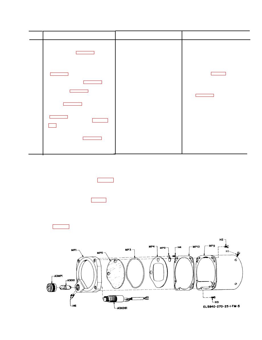
Figure 4-3. Indicator case, exploded view. |
|
||
| ||||||||||
|
|
 TM 11-5840-270-24-1
b. C h a r t .
Item
Probable cause
Corrective action
No.
Symptom
Pointer mechanism out of
R e p l a c e the mechanism
P o i n t e r moves off center when in-
1
balance.
dicator is rotated about the
horizontal axis (para 4-17).
Flag mechanism out of balance.
Replace the mechanism
Warning flag changes position or goes
2
out of view when indicator is
rotated about the horizontal axis.
Change series resistor
R1
as
I n c o r r e c t resistor R1 in com-
Terminal resistance is not 1000 ohms
3
p e n s a t i n g network.
r e q u i r e d . (fig. 4-5)
Defective mechanism . . . . . . . . . .
Replace mechanism
C u r r e n t required for deflection of
4
pointer is incorrect (para 4-21).
a. R e p l a c e m e c h a n i s m
a. Defective mechanism. . . . . . .
Current required for deflection of flag
5
b. S p r i n g t e n s i o n o n a r m a t u r e
b. Readjust the spring tension
is incorrect (para 4-22).
i n mechanism is incorrect.
a. D i r t y m e c h a n i s m o r m e t e r
Pointer does not leave stop at correct
a. C l e a n
stop,
6
clean
mechanism.
stop.
current (para 4-23).
b. R e p l a c e m e c h a n i s m
b. Defective mechanism. . . . . . .
7
Defective mechanism. . . . . . . . .
R e p l a c e mechanism
P o i n t e r response time is incorrect
Beacon light is inoperative (para 4-
a. Lamp is defective . . . . . . . .
a. R e p l a c e l a m p
8
b. L a m p s w i t c h o r l a m p h o l d e r
b. Replace if required
is defective.
Open case and inspect for solder
Electrical short between case and a
Internal wiring shorted. . . . . . .
9
or wire touching case. Remove
pin on a connector (para 4-26)
a n y excess solder and move
component leads or wiring to
prevent shorting to case.
Section Ill. DISASSEMBLY AND REASSEMBLY
a. Remove six screws H2 and two screws H3
4-8. Case Removal
from rear of case flange and lift case MP9 from
bezel assembly. Remove gasket MP10.
washers H10 securing smaller connector J2.
b. Remove four screws H4 and four clips MP2.
b. Disconnect three leads from connector J2
c. Remove mask MP4 and gasket MP3.
Remove connector J2 and gasket MP13.
d. Unscrew dimmer cap A3MP1 and remove
A3DS1.
slide the mechanism assembly out the rear of the
e. Loosen two setscrews H 6.
case.
f. Unscrew socket A3XDS1 and remove mom
4-9. Disassembly of Indicator Case and Bezel
bezel MP1.
Assembly
Figure 4-3. Indicator case, exploded view.
4-3
|
|
Privacy Statement - Press Release - Copyright Information. - Contact Us |
