 |
|||
|
|
|||
|
Page Title:
Section I. PRINCIPLES OF OPERATION |
|
||
| ||||||||||
|
|
 CHAPTER 4
D I R E C T AND GENERAL SUPPORT MAINTENANCE
Section I. PRINCIPLES OF OPERATION
4-1. General
"sum" and "difference" are obtained from the
same output.
The marker beacon lamp flashes a coded signal as
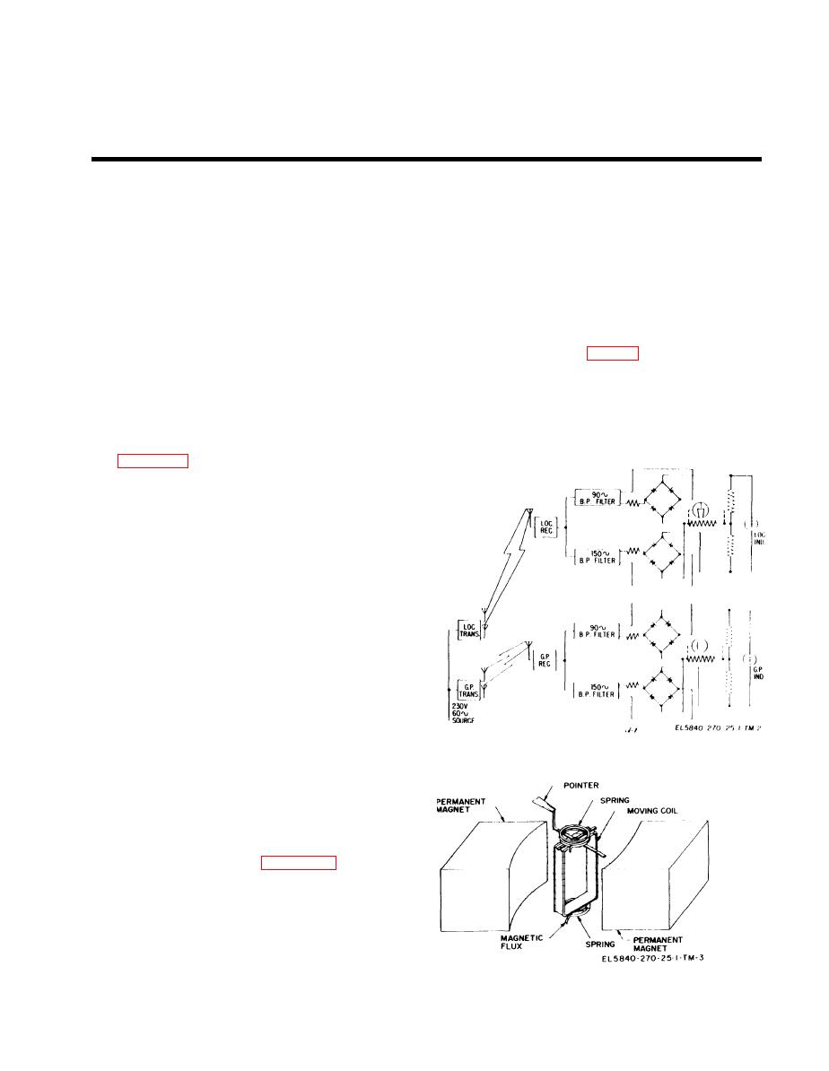
d. The mechanisms Ml, M2, M3, and M4 are
the aircraft passes over each of the three marker
similar in construction and operating principle.
beacon transmitters. These transmitters are located
Each mechanism is a permanent magnet moving-
at approximately 4.5 miles, 1.0 mile, and 200 feet
coil type microammeter, which consists essentially
from the end of the runway. The outer marker
of a moving coil mounted and pivoted in the field of
beacon is identified by a 2 dashes-per-second signal,
a permanent magnet (fig. 4-2). Current flowing
the middle marker beacon by a 6 dots-per-second
through the coil causes the coil to rotate, which
signal and the boundary marker beacon by an
moves the attached pointer across the scale. The
unkeyed signal. As these signals are received, the
deflection of the moving coil is proportional to the
pilot checks the distance to the runway and the
current flowing through the coil, and hence, to the
altitude at the time of crossing.
strength of the signal received from the aircraft
4-2. Block Diagram Analysis
receiver.
the Instrument Approach System. The signal is
split at the ground transmitter; one section is
modulated at 90 cycles per second, and the other is
modulated at 150 cycles per second. For con-
venience in flight, these sectors are designated as
blue and yellow sectors and the indicator face is
marked with corresponding blue and yellow sec-
tors. The blue sector is transmitted to the right of
the beam in respect to the landing aircraft and the
yellow sector is transmitted to the left of the landing
aircraft. The signals are received by the localizer
receiver and separated by frequency discriminators
or hand-pass filters, individually rectified and
recommended by differential connection of the
rectifier output to actuate the pointer. The glide
path transmitter and receiver operate in a similar
manner to establish the glide path intelligence.
Figure 4-1. Simplified block diagram of indicator in instrument
b. The vertical pointer supplies a visual in-
approach system.
dication of the lateral position of the aircraft with
rcspect to the on-course signal of the localizer beam.
The horizontal pointer shows the relationship of the
aircraft to the glide-path beam. When the aircraft is
properly aligned on the approach path, the pointers
are crossed at the center of the dial.
connections of the flag mechanism in the output
circuit of the receivers. The warning flags operate
from the summation of the rectifier outputs while
the pointers operate from the difference of these
outputs. T h i s arrangement provides positive
"nonoperating" signals by virtue of the fact that the
Figure 4-2. Permanent magnet, moving-coil type mechanism.
4-1
|
|
Privacy Statement - Press Release - Copyright Information. - Contact Us |
