 |
|||
|
|
|||
|
Page Title:
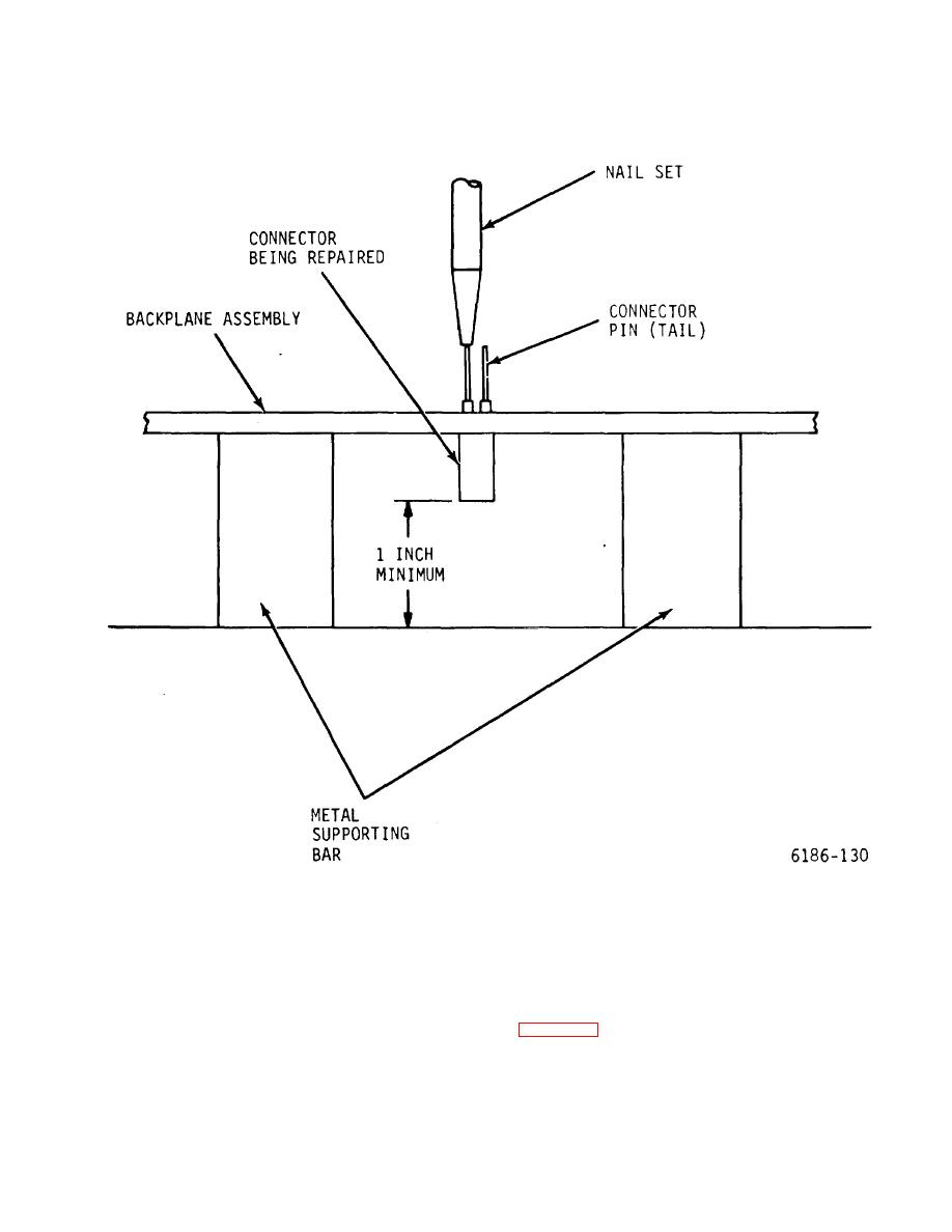
Figure 6-14. Backplane Connector Repair Diagram |
|
||
| ||||||||||
|
|
 T.O. 31W2-2GSC24-2
TM 11-5805-688-14-1
NAVELEX 0967-LP-545-3010
Figure 6-14. Backplane Connector Repair Diagram
The following paragraphs present replacement
captive retaining screws as follows:
procedures for semipermanently mounted chassis parts.
1. Place knurled heat of fastener being
replaced between opened jaws of a bench vise as shown
6-70. CAPTIVE SCREW REPLACEMENT.
in figure 6-15.
6-71. Captive retaining screws are provided as part of
2. Using a center punch, carefully drive screw
the printed circuit card access cover, the power supply
portion of fastener
access cover, and the cooling blower panel. Replace
6-51
|
|
Privacy Statement - Press Release - Copyright Information. - Contact Us |
