 |
|||
|
|
|||
|
Page Title:
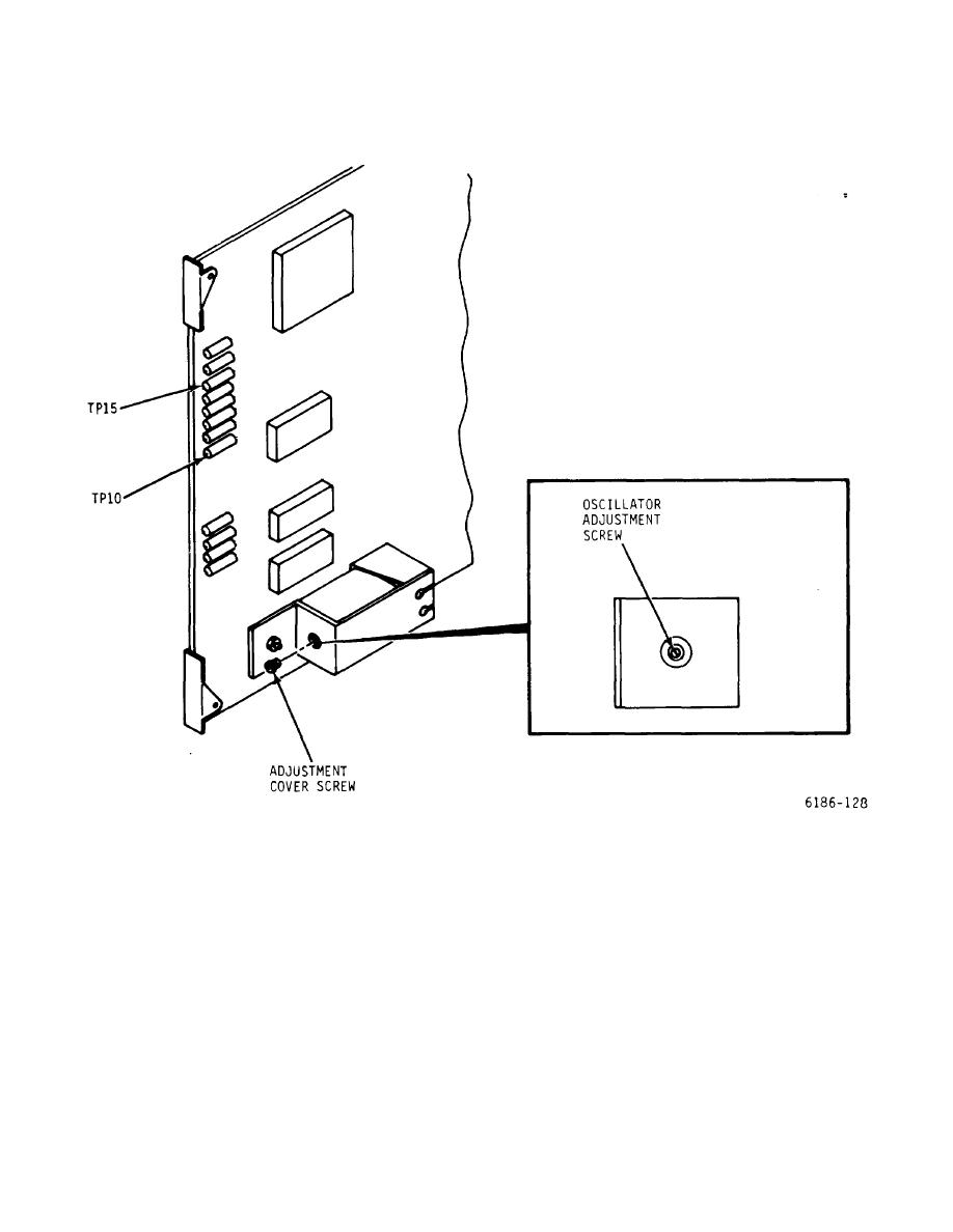
Figure 6-8. RT Card - Test Point and Alignment Location Diagram |
|
||
| ||||||||||
|
|
 T.O. 31W2-2GSC24-2
TM 11-5805-688-14-1
NAVELEX 0967-LP-545-3010
\
Figure 6-8. RT Card - Test Point and Alignment Location Diagram
prescribed limits. The calibration is performed, using a
NOTE
Hewlett-Packard Model 5245M frequency counter.
Perform calibration procedures as follows:
If the transition encoder/timing recover
(TE/TR) assem-bly oscillators are to be
NOTE
calibrated at this time, the printed circuit
card access cover may be left off.
To ensure proper calibration, allow the
frequency counter to warm up for
approximately 15 minutes before making
TE/TR card is performed to ensure that the frequency of
frequency measurements.
the
timing
recovery
is
within
6-35
|
|
Privacy Statement - Press Release - Copyright Information. - Contact Us |
