 |
|||
|
|
|||
|
Page Title:
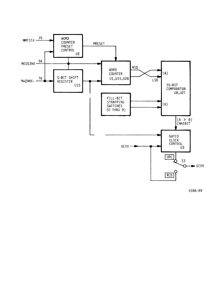
Figure 5-13. RCB Card, Coarse Rate Conversion Circuits - Block Diagram |
|
||
| ||||||||||
|
|
 T.O. 31W-2GSC24-2
TM 11-5805-688-14-1
NAVELEX 0967-LP-545-3011
Figure 5-13. RCB Card, Coarse Rate Conversion Circuits - Block Diagram
5-183. The coarse rate activity detector is a retriggerable
5-184. The timing comparator compares the identical
one-shot multivibrator that is held in conduction by bit
timing outputs of timing receiver No. 1 with those from
count 512 from the word counter in the coarse rate
timing receiver No. 2. When the timing signals are not
conversion circuits. When bit count 512 is missing, the
the same, the output of the comparator sets the timing
multivibrator's duty cycle expires and the coarse rate
error latch, which, in turn, applies a timing error signal to
error signal is applied to the composite error detector.
the composite card error detector.
5-44
|
|
Privacy Statement - Press Release - Copyright Information. - Contact Us |
