 |
|||
|
|
|||
|
Page Title:
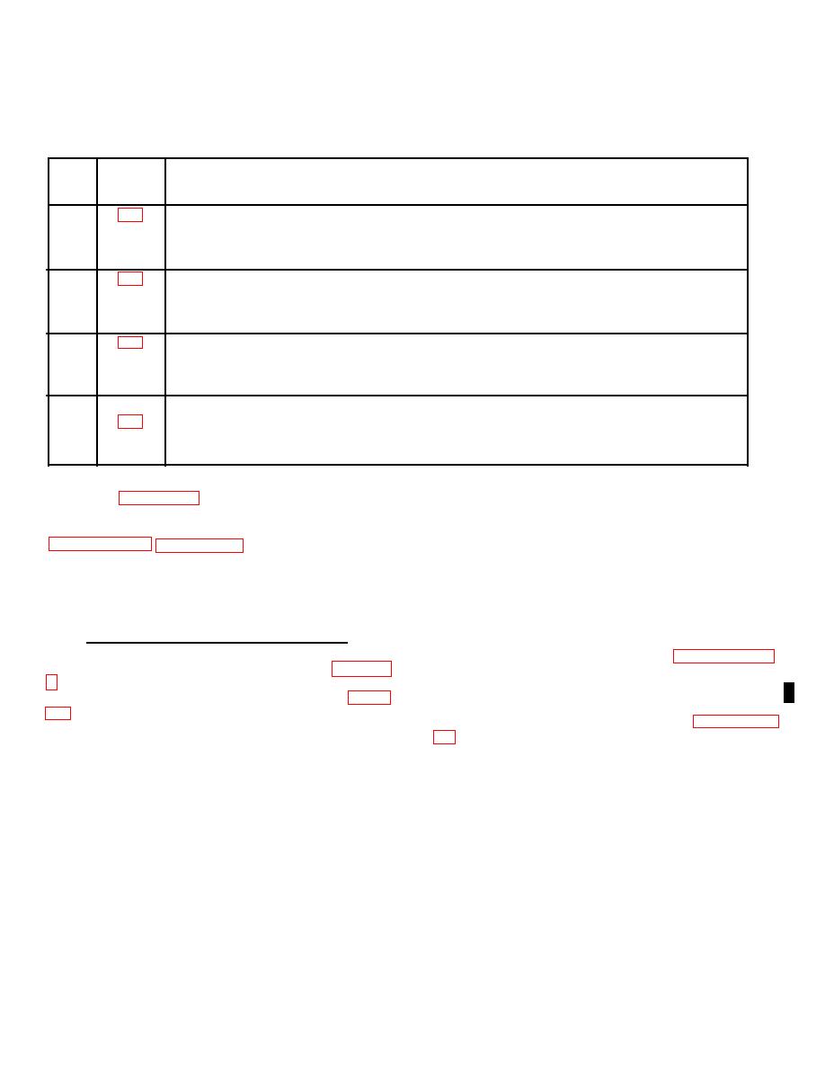
Table 3-2. Configuration Worksheet Data |
|
||
| ||||||||||
|
|
 T.O. 31W2-2GSC24-2
TM 11-5805-688-14-1
NAVELEX 0967-LP-545-3010
Table 3-2. Configuration Worksheet Data
Sheet
Figure
No.
No.
Function
1
Provides information necessary to configure channel electronics portion of multiplexer
function. Includes information defining channel input rates and forms, and
instructions as to type f channel card to be used in processing each channel input.
2
Provides information necessary to configure common electronics portion of multiplexer
function. Includes information defining output rate (Ro) and form, port assignments,
and timing source.
3
Provides information necessary to configure channel electronics portion of
demultiplexer function. Includes information defining channel output rates and
forms, and instructions as to type of channel card to be used in processing each
channel output.
4
Provides information necessary to configure common electronics portion of
demultiplexer function. Includes information defining serial data high-speed input
rate (Ro), port assignments, and timing source.
No. 1 in the selected system. In the duplex arrangement
3-34. On sheet 1 of the configuration worksheets, each
shown in figure 3-4, both the multiplexer and
channel's input rate is entered in the applicable INPUT
RATE (BPS) Rc block. Since the channel 2 input is
demultiplexer are used, but with different sets of channel
data rates and forms. A mix of voice, Type I, and Type II
voice, the word VOICE is entered instead of a data rate.
Next, the type of channel card to be used for the
to the multiplexer set. The inputs are multiplexed into a
processing of each input channel is listed in the
single 48.0-kbps output data stream. The demultiplexer
applicable CARD TYPE TE/TR, VE, or RCB block.
accepts a serial 1.536-Mbps input data stream and
Thus, for channel 2, an X is entered in the VE (voice
demultiplexes it into five Type I channel data outputs.
encoder) block. Channels 1 and 3 process Type II data
inputs that do not have an associated timing input. Such
3-32. MULTIPLEXER CHANNEL ELECTRONICS.
inputs must be processed with a transition
encoder/timing recovery (TE/TR) card (paragraph 3-28)
3-33. Sheet 1 of the configuration worksheets (figure 3-
operating in either the transition encoder (TE) or timing
recovery (TR) mode. A maximum input rate of 400 bps
cards. As shown in the configuration example in figure
can be processed in the TE mode, and KRp must be
three times the selected input rate range (paragraph 3-
and Type I and Type II data inputs.
Change 2 3-9
|
|
Privacy Statement - Press Release - Copyright Information. - Contact Us |
