 |
|||
|
|
|||
|
|
|||
| ||||||||||
|
|
 TM 10-3990-203-13&P
b. Support the elevated end with blocks.
h. Thread locknuts (3) onto bolts (2) and tighten by
hand.
i. Use a 3/4 inch box wrench on locknuts (3) and a
3/4 inch socket and ratchet on bolts (2) to tighten
securely.
Secure the ground end of the ramp to prevent
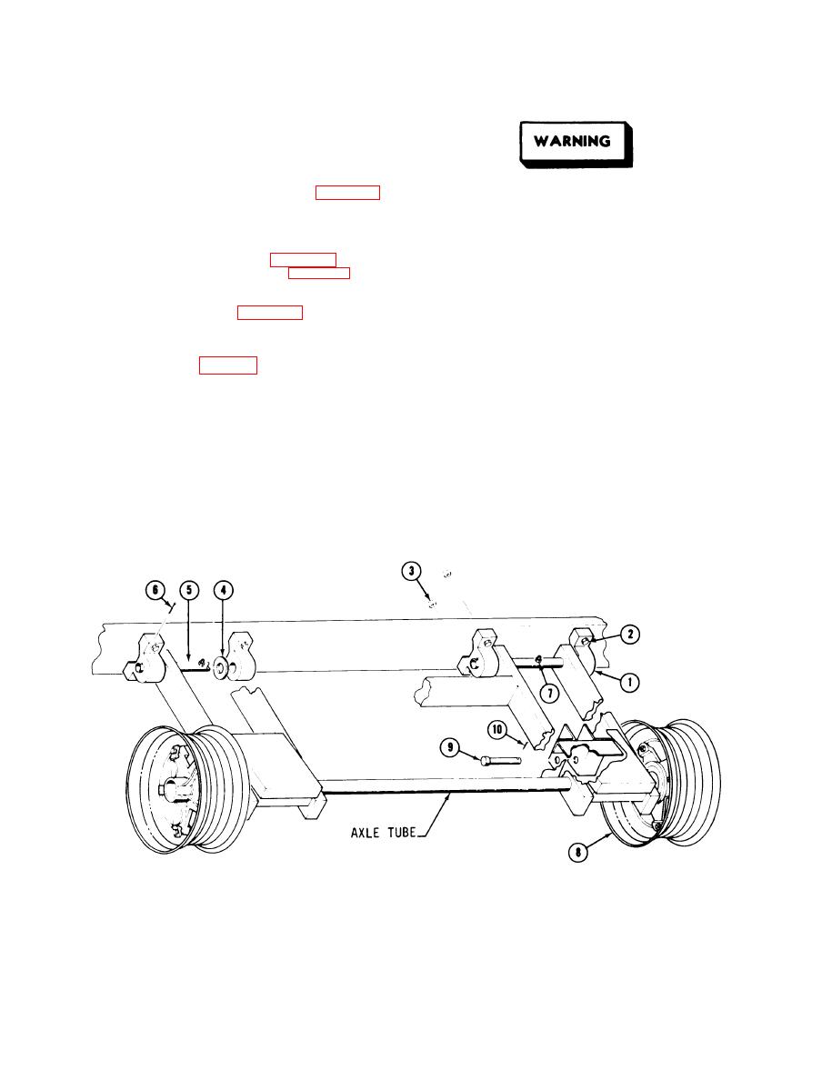
j. Attach hydraulic lift cylinders (1, Fig. 5-13)
the ramp from sliding off the blocks.
to the undercarriage by aligning the mounting holes
on the lower half of cylinder (2) with the holes in
c. Place the pump control valve in the LOWER
cylinder rod mounting brackets (3).
position.
k. Slide lower clevis pins (9, Fig. 5-6) through
d. Place blocks under the undercarriage to sup-
cylinder rod mounting brackets (3, Fig. 5-13) and
port the ramp when wheel and hub assemblies are
cylinder rod.
removed.
l. insert cotter pins (10, Fig. 5-6) through the
e. Place a 3/4 inch socket and ratchet over rim
holes in the ends of clevis pins (9). Secure cotter
bolt (9). Loosen and remove bolts and rim clamps
pins.
(lo).
5.5.6 Hub Assembly (Fig. 5-7)
f. Remove tire (1) and rim (2) as a unit.
5.5.6.1
Disassembly
g. Remove grease cap (8) from hub (3).
a. Using the hydraulic pump, elevate the ramp
h. Remove cotter pin (7) from axle (6).
enough to clear the wheels.
Figure 5-6. Undercarriage Assembly
5-8
|
|
Privacy Statement - Press Release - Copyright Information. - Contact Us |
