 |
|||
|
|
|||
|
Page Title:
Figure 3-9. Open view-mode 5027 RC. |
|
||
| ||||||||||
|
|
 TB 9-2920-225-34-1
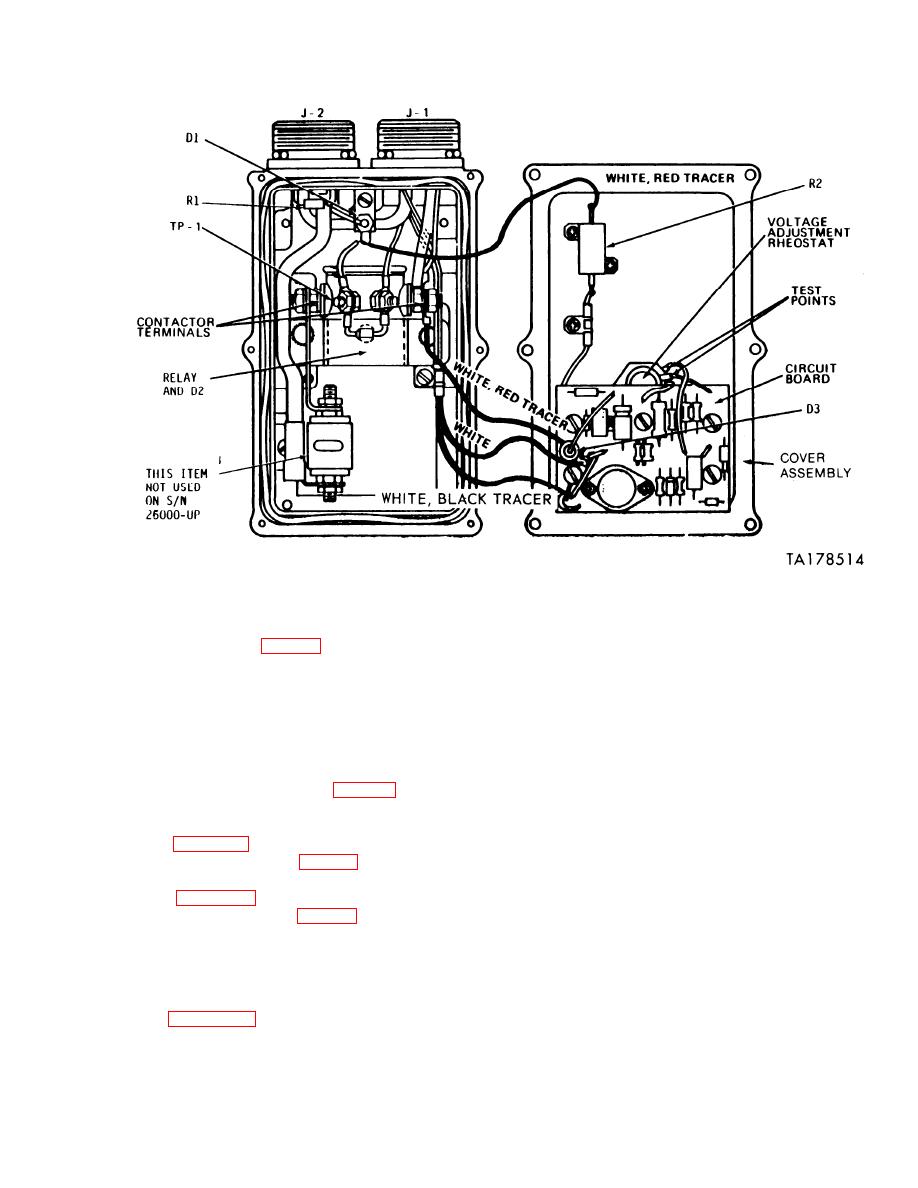
Figure 3-9. Open view-mode 5027 RC.
f. Functional Check. Check the performance of
(2) Place ohmmeter probes to the terminals
the regulator on the test stand and make final
of the rheostat (see figs. 3-9,3-10, and 3-11).
voltage adjustments. Voltage output should read
(3) Rotate rheostat fully clockwise; reading
28 volts. If the regulator does not function prop-
should be approximately 45 ohms.
erly, perform the following:
(4) Rotate rheostat fully counterclockwise,
reading should be less than 5 ohms.
(1) Check wires and connections.
(5) If other readings are obtained, replace
(2) Replace circuit board or cover assembly.
the rheostat.
(3) Perform bench test procedures.
d. Power Resistor R2. Place ohmmeter probes
across power resistor R2 (see figs. 3-9, 310, and
NOTE
3-11). Meter should read approximately 30 ohms.
e. Detailed Circuit Checks.
After final repair, check regulator on the
(1) Table 3-4 contains "power off" resistance
test stand.
checks of the circuit (see figs. 39, 310, and 311
If the regulator still does not function correctly
for test points).
it will be necessary, if local skills permit, to test
(2) Table 3-4 contains "power on" voltage
each component. All the parts should be checked
checks of the circuit (see figs. 3-9, 3-10, and 3-11
with an ohmmeter and the capacitors checked with
for test points ).
a capacitance meter. The circuit board traces
NOTE
should rechecked with an ohmmeter to make sure
that there are no cracked traces. Traces with hair-
Power transistors on the circuit board
line cracks will show good at lower temperatures
and heat sink can be checked as outlined
and will tend to show open circuit at higher tem-
on figures 31 and 32. However, since
peratures. If the board seems good at room tem-
they are soldered into the circuit, re-
perature, but the regulator still fails, this could
moval and replacement is more time con-
be the cause.
suming.
3-11
|
|
Privacy Statement - Press Release - Copyright Information. - Contact Us |
