 |
|||
|
|
|||
|
|
|||
| ||||||||||
|
|
 TA007231
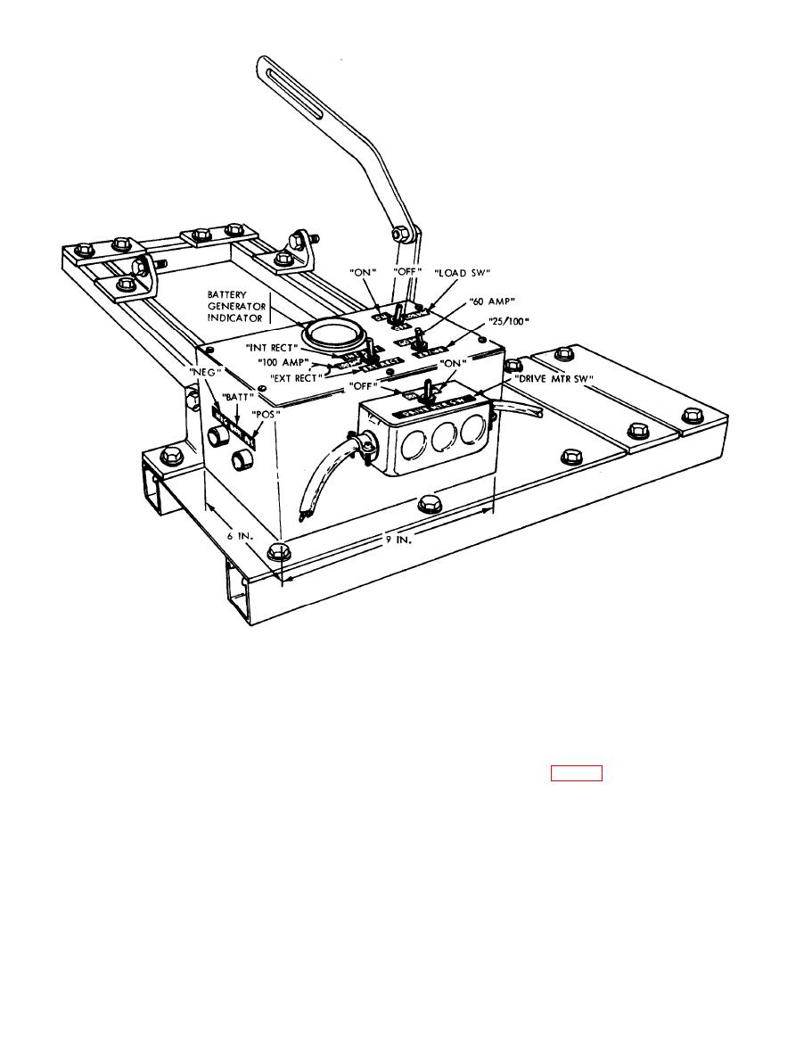
Figure 4. Frame assembly and control cabinet.
5. Control Cabinet. a. Exterior cabinet dimen-
left end plate instead of the right end plate
sions (fig. 4).
as shown in the electrical schematic drawing
b. Wiring diagram of internal cabinet components
(fig. 5).
c. The indicator (voltmeter) FSN 6625-321-6365
6. General. This tester has been designed and
is a military standard item and the wire FSN
manufactured with connectors that fit only the
6145-705-6678 is available in bulk quantity.
d. Each of the three toggle switches can be any
It is not possible to connect the wrong component
two-pole, double-throw unit with a contact rating
to the wrong receptacle.
of ten.
e. The battery cables will be fabricated with an
a. Place the tester on a work bench so that
alligator clamp at one end and a telephone-type
jack at the other. The jack receptacles in the cabinet
the generator mounting bracket and the belt ten-
will be marked positive and negative to insure
sion adjusting lever arm, when extended, will
proper polarity when connected to the batteries.
rest on the bench (fig. 1). Secure the tester to the
bench.
NOTE
b. Check the battery, load, and motor switches
When fabricating the cabinet, it is better
and insure that they are in the OFF position
to install the battery jack receptacle in the
(fig. 6).
6
|
|
Privacy Statement - Press Release - Copyright Information. - Contact Us |
