 |
|||
|
|
|||
|
Page Title:
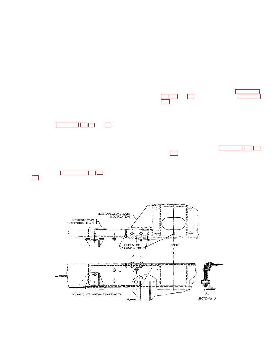
Figure 48. Repair at Trapezoidal Plate - Upper Flange |
|
||
| ||||||||||
|
|
 TB 9-2300-247-40
c.
Prepare sketches and/or templates for the
NOTE
conditions and locations of the proposed repair.
Individual templates for each crack and location
The
exact
doubler
location
may be used as a pattern and contour cutting to
determines the length of the cutout in
fit the particular rivet and frame hole location.
the jounce bracket.
d. Join the two segments of steel plate at right
WARNING
angles,
fitting
pieces
corner-to-corner
longitudinally and weld inside and outside. The
Use Only effective chip guarding
outer corner weld shall be a 3/8-inch fillet type
equipment, protective equipment and
conforming to MIL-STD-1261, Class I.
protective clothing (goggles, shields,
gloves aprons, etc when doing any
e. Fabricate doubler plate as shown in Figures 42,
drilling, grinding, or welding. Failure
to follow this warning could result in
injury to personnel.
f.
Bevel the doubler at the gap to a 450 angle.
b. Use an oxyacetylene torch, make cut-outs in the
jounce bracket with a maximum 5/32-inch gap
g. Securely bolt the doubler to the bracket using
as shown in Figures 42, 45, 48, and 50.
new No. 8 UNF bolts, washers, and locknuts.
Torque bolts in accordance with
NOTE
h. Add spacer as shown and secure doubler to the
Due to the various locations and
rail and repair as shown in Figures 42, 45, 48,
types of cracks which may develop in
and 50.
vehicle frame rails, the widths,
lengths, and contours of doublers
i.
Thoroughly clean repaired
surfaces
and
fabricated
will
vary
with
the
surrounding area of repair.
application. Figures 42, 45, 51, and
j.
Prime and paint repair area and surrounding
recommended
for
doubler
surfaces as specified in TM-43-01 39.
construction.
Figure 48. Repair at Trapezoidal Plate - Upper Flange
42
|
|
Privacy Statement - Press Release - Copyright Information. - Contact Us |
