 |
|||
|
|
|||
|
Page Title:
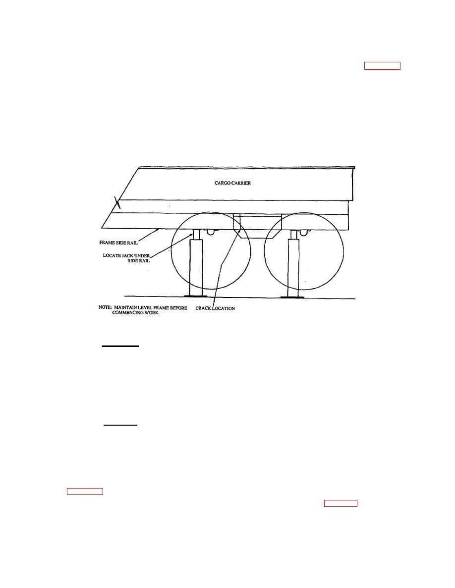
Figure 24. Location of Jacks or Supports |
|
||
| ||||||||||
|
|
 TB 9-2300-247-40
Floor surface must be flat within 1-inch in 24 feet. Floor
e.
Carefully jack up and evenly support the
clean of dirt, grease, oil, or debris.
vehicle frame to gain access to the area to
be repaired as shown in Figure 25. Provide
Equipment Condition: Vehicle empty and vehicle
firm support directly under the area to be
undercarriage clean and completely free of mud,
repaired and as shown.
dirt, and debris.
f.
Remove hold down bolts securing cargo
d.
Perform the necessary removal of
area and raise cargo area approximately 4
components, service lines, electrical wiring,
to 6 inches of clearance above side rails to
etc., as required to gain access to the
gain access to for working space.
proposed repair.
g.
Lower or remove rear axle assembly, side
plate, and frame bracket.
Figure 24. Location of Jacks or Supports
i.
If the break (crack) does not extend through
WARNING
the entire cross section of the rail, a 3/16-
Use Only effective chip guarding
inch diameter hole may be drilled at the
equipment, protective equipment and
extreme edges of the crack. This will
protective clothing (goggles, shields,
reduce the concentration of the defect at
gloves aprons, etc.) when doing any
the tip of the break.
drilling, grinding, or welding. Failure
to follow this warning could result in
j.
Using a suitable grinder, bevel the edges of
injury to personnel.
the break and follow the repair procedures
indicated in paragraphs m thru y.
CAUTION
When cutting at the edges of frame
k.
Separate the vehicle frame at the break to
rail break, care should be taken not to
be repaired and scarf or bevel the edges of
remove excessive metal and create
the broken sections and cut a V-shaped
the need for an unnecessarily large
groove at both sides of the break.
welded area.
l.
To assure accuracy of alinement, butt the
h. Remove rivets and bolts as required and as
two broken sections together and clamp
described in Chapter 1.
with C-clamps, a straight edge or angle iron
as shown in figure 28.
23
|
|
Privacy Statement - Press Release - Copyright Information. - Contact Us |
